| PSU-Troubleshooting - found this in a
forum, dunno who is author but send me you name if you da man
Troubleshooting with a multimeter
NOTE: This testing applies only to the standard ATX PSU, it does not
apply to proprietary PSU's (ie: older Dell's ) which use a different pinout
arrangement for their ATX connectors (non-standard).
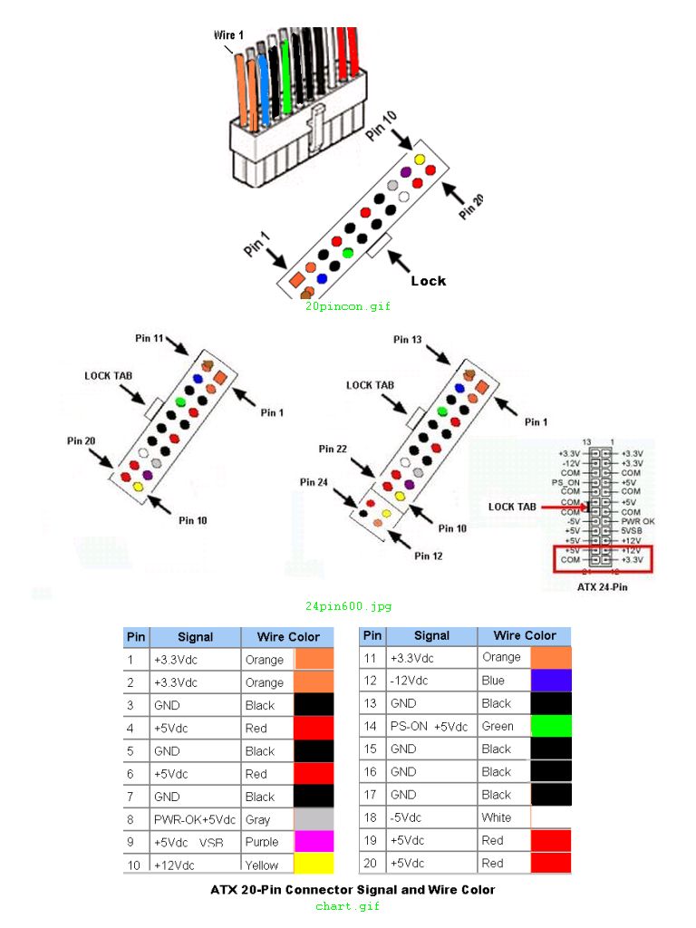
20 and 24-Pin
Connectors: The 24-Pin connector has an additional 4 pins attached to one
end of the connector. The top 20-Pin section is electrically identical to the
original 20-Pin ATX connector. Due to the additional connections the numbering
sequence changes, so if you have a 24-Pin connection then make that adjustment
when comparing any numbers shown below. (Refer to the pictures
below.)
_____________________________________________
If you suspect a
part has failed but not sure if it's the Power Supply (PSU), Processor (CPU), or
motherboard at fault, you can use a multimeter to aid in locating the probable
cause.
Testing the DC voltages
With the
20-pin ATX connector in the motherboard socket and AC power on, the DC voltages
have to be probed from the backside of the connector by inserting the probe tip
alongside the wires to contact the connector pins.
Set meter to read
20Vdc. Refer to ATX 20-pin connector pinout chart (below) and put the black
probe tip to a GND pin (ie: black wires on pins 15, 16, 17).
With the Red
probe tip...
1. Check Pin 9 (Purple, VSB) is about 5V. This is the
standby voltage and is always on when the power supply is live to an AC source.
If not 5V then problem with PSU, or a possible short circuit in motherboard or a
peripheral device has caused the PSU to auto-shutdown.
2. Check Pin 14
(Green, PS_On) should be about 3~5V. If PS_On is zero Volts and VSB okay then
disconnect the pc case Power On switch to see if voltage comes up, if so then
bad switch.
3. Press the pc case Power On switch and PS_On should drop
to ~0V.
If no change, the suspects are faulty switch or CPU. If the
motherboards PS_On pins are accessible by removing the pc case's power on leads
then short the 2 pins with a light tap from a screwdriver tip to trigger the
power on. Another way is to use a jumper wire to short PS_On to GND. If no
change in PS_On then probable fault is CPU.
With PS_On at
~0V...
4. Check Pin 8 (Gray, Power_OK) should be 3~5V to signal the
CPU that power is okay to start. If not above 2.5V then signal not high enough
to trigger CPU for start.
5. Pressing the Reset button (or shorting
the reset pins) will make Power_OK go low (0V), and when released should go back
up to 3~5V.
(Note, this may not happen if the manufacturer has used a 'soft'
method to trigger the Reset.)
NOTE: If CPU doesn't POST when Power is
first turned on but does POST when Reset triggered, then the initial power
demand (by all devices) is to high for the PSU to handle, need to replace PSU
with a better one.
With Power_OK at ~5V...
6. Refer to chart
and check voltages are at proper levels on the 20-pin connector and all the
peripheral power connectors inside the case.
+3.3v pins 1, 2, 11 (Orange
wires)
+5V pins 4, 6, 19, 20, (Red wires)
+12V pin 10 (Yellow
wires)
-5V pin 18
-12V pin 12
Note: Depending on the quality of the
PSU, there may be nominal voltages detected on the +5V and +12V lines with AC
live and pc power off. Always remove AC power, and wait at least 30 seconds to
allow residual power to drain before working in pc case.
Testing for Continuity
UNPLUG THE COMPUTER FROM THE
AC POWER, and wait 1 minute to allow residual power to drain off.
Set
the multimeter to the lowest Ohms ( Ω symbol) value, a typical value is
200.
Touch the probe leads together to zero the meter, note the value if it's
not quite zero (live zero), this value will be used to indicate a short circuit
during testing. Touch the two probe tips to bare metal inside the pc chasis,
should get same zero reading.
Testing the PSU for short and open
circuits...
Remove ATX connector from motherboard.
1. Keeping one
probe on chasis, use other probe to check PSU's AC ground pin and the DC
connectors black wire pins are reading zero. Any value other than zero indicates
faulty grounding-replace PSU.
2. Keeping one probe on chasis, use
other probe to check the connectors non-black wires are non-zero (if a colored
wire reading less than 50 suspect a problem).
Testing the Motherboard for
open circuit...
Remove the CPU from motherboard socket before doing this
test.
Refer to ATX 20-pin connector pinout chart for GND pin locations. Use
PSU's 20-pin connector to familiarize yourself with the board's connector. Only
test the GND pins, the multimeter's internal voltage may damage a component
connected to the other pins.
3. Keeping one probe on chasis, check GND
pins 3,5,7,13,15,16,17 should have the zero reading, any other value suspect a
fault-check board is properly installed and repeat test.
If still non-zero
remove board and test GND pins again, with one probe touching the metal ring at
a mounting hole, if still non-zero then motherboard faulty-replace it with
another board.
.
You are here: Home-Computer Tips & Help-Hardware-PSU Troubleshooting
Previous Topic: Research-aholic
|